How to Make a USB Composite Device with HIDmaker FS - Part 1
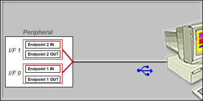
One of the capabilities that makes HIDmaker FS really powerful is its ability to make a USB Composite Device. A Composite device is a single piece of hardware, that connects to the PC by a single USB cable, but which acts as if it contained multiple independent USB devices inside it. Each one of those seemingly independent devices (labeled "I/F 1" and "I/F 2" in the diagram below) is actually just a separate USB Interface .
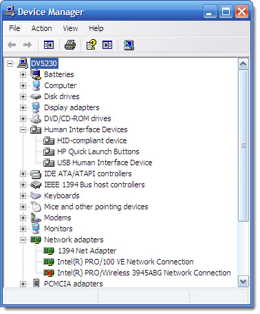
You can see that this is so in Windows Device Manager. When we connect a USB Composite Device to our PC, and look at it in Device Manager, we actually see what looks like more than one device. In fact, when we connect the cable to our one device, Device Manager shows that TWO entries have been added.
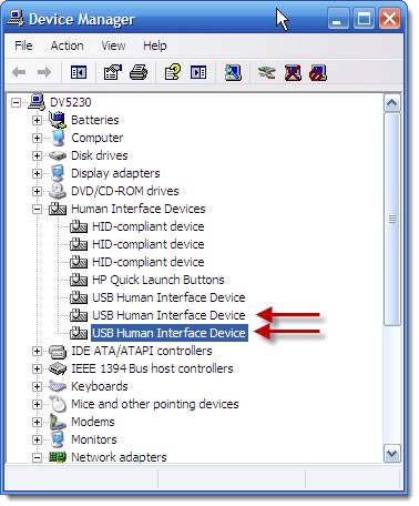
Closer inspection in Device Manager shows that these are actually two Interfaces connected to the same USB port. And when we disconnect the one USB cable from our device, those two entries disappear again.
Similarly, here is what this same Composite looks like in AnyHID 's Browse HIDs display. You can clearly see what appears to be two separate devices, but they really are from the same physical device.

And AnyHID can open, and talk to, either one of these two Interfaces as if it were a completely separate device.

WHY You Might Want to Make a USB Composite Device
Because the PC host treats each USB Interface as if it were a completely separate device, it is possible for you (or for HIDmaker FS) to create a PC program that only talks to ONE of those USB Interfaces in your device. This works through the magic of Cooperative Multitasking. Alternatively, you can have HIDmaker FS create a single PC program that talks to all of the USB Interfaces it has created in your device (which is what HIDmaker FS does by default).
The current version of HIDmaker FS can make USB Composite Devices that contain up to 3 USB Interfaces, all of which have to be USB HID class Interfaces. You can do quite a lot with that, because different Interfaces can be used in a lot of different kinds of ways:
- In the most common approach, each USB Interface provides a different kind of functionality. Your device acts as if two or more separate devices (e.g. a keyboard Interface and a separate Mouse interface),
- Or, each Interface can act like a different kind of data channel
- Or, one Interface could provide the main functionality, and another Interface could be used to just change settings or parameters used by the first Interface. One example might be a data acquisition device: the first Interface might be used for reading the actual data from the device, while the second Interface might be used to change or read back the current settings of amplifier gains inside the device.
What are some ways that YOU might use multiple USB Interfaces in a project of your own?
When you make the simplest kind of HIDmaker project, which we call a "Normal" device type, you are making a device that has only a single USB Interface .

A USB Composite Device is just a device that contains more than one USB Interface. And the process of making a USB Composite Device in HIDmaker FS is really simple - you just define data for more Interfaces, that's all.
>
Saving Your Variables As An Interface Data Set
Of course, you expect to be able to save your entire HIDmaker project, which goes into a *.hpr file. To help you remember, the extension ".hpr" comes from "Hidmaker PRoject."
Here's a really important thing you can do with HIDmaker FS. To make your future projects easier, you also have HIDmaker/s Visual Data Designer save just the set of data items used by one USB Interface - that is, the set of USB transfer variables that you have defined for that one Interface. The file type for these data items has an extension of *.rdi. To help you remember, the extension ".rdi" comes from "Report Data Items."
We'll call the data items contained in a single USB Interface , as stored in a single *.rdi file, an Interface Data Set.
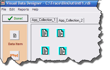
Once you have saved an Interface Data Set to a *.rdi file, then you can easily re-use this USB Interface in future HIDmaker FS projects. All you need to do is click that "Define Data" button in the HIDmaker FS wizard, to open the Visual Data Designer .

Then, just tell the Visual Data Designer to open the *.rdi file that contains the Interface Data Set that you want. Visual Data Designer will then load those data items and use them for this USB Interface .
The Basic Idea: Re-Using Several Interface Data Sets
In fact, we have used that capability as we built up some of the sample projects that we supply with HIDmaker FS . Here is a summary of the steps we took to make a Composite Keyboard / Mouse sample project:
- We made a sample Keyboard project, and saved its Interface Data Set in a file called "boot101.rdi" (that is, an Interface Data Set for a standard 101 key USB keyboard, that can even work at boot time, when Windows hasn't started up you and only the ROM BIOS of your PC is running).
- We then made a sample Mouse project, and saved its Interface Data Set in a file called "BtMouse.rdi" (that is, an Interface Data Set for a standard USB Mouse, that can even work at boot time if the ROM BIOS in your PC uses a mouse).
- Finally, we were able to quickly convert these to a composite Keyboard and Mouse device by:
- First telling HIDmaker FS to create a Composite device type
- Clicking the Define Data button for the first Interface and telling the Visual Data Designer to use the contents of file boot101.rdi, the keyboard data set, as the variables for this first USB Interface .
- When we exited the Visual Data Designer , we selected the Endpoints we needed for the first Interface.
- Then we selected the second Interface, clicked the Define Data button to open the Visual Data Designer, and told the VDD to use the contents of file BtMouse.rdi, the mouse data set, as the variables for this second USB Interface .
- When we exited the Visual Data Designer , we selected the Endpoints we needed for the second Interface.
At this point, we were ready to generate code for our USB Composite Device.
Next Time: We'll show you, step by step, how to use HIDmaker FS to build up a USB Composite Device of your very own. And we'll add a few extra tricks, too!

Got a comment on what you just read? Let us know - just add a comment below.
We'd love to hear from you!